


Ultimate Resolution of Atomic Force Microscopy
True Non-Contact AFM for the best AFM resolution available
When using the Non-Contact (NC) mode with a very small tip-sample distance, even a slight deviation of tip-sample interaction force from the set point can be fatal. This is why the tip has to be farther from the sample surface in conventional NC mode, resulting in poor resolution.
Implementing an NC mode with small tip-sample separation has been a very challenging task, but Park Systems has a solution. Park AFM features an NC mode that surpasses the resolution of all AFMs that came before it, even those using contact mode. This makes Park AFM the best choice for imaging soft biological samples as it provides extremely high resolution imaging without damaging the sample (see "True Non-Contact AFM for soft biological samples" for details).
Created by the original pioneers of Atomic Force Microscopy (AFM) technology after 4 years of intensive product development, Park AFM represents the refined vision of breakthroughs in every aspect of modern AFM technology (see "Development of Crosstalk Eliminated Atomic Force Microscopy" for details). Park AFM is the first and only AFM on the market that realizes the promise of a True Non-Contact mode in every way.
This new technology achieves an unprecedented tip-sample distance, combined with superb tip and sample preservation. The advantages of True Non-Contact™ Mode enable the ultimate resolution of AFM and measurement accuracy that are without peer in the AFM industry (see "What is the Ultimate Resolution of AFM?" for details).
Non-Contact AFM: The Principle
Non-Contact AFM (NC-AFM) is one of several vibrating cantilever techniques in which an AFM cantilever is vibrated near the surface of a sample. The spacing between the tip and the sample for the Park AFM's NC-AFM mode is on the order of tens to hundreds of angstroms. This spacing is indicated on the van der Waals curve of Figure 1 as the Non-Contact zone. There are two major forces, the static electric repulsive force and attractive force, existing between atoms a short distance apart: The static electric repulsive forces (Fion) between ion cores and the static electric attractive forces (Fel) between valence electrons and ion cores. When the distance between the atoms at the end of the probe tip and the atoms on the sample surface becomes much shorter, the repulsive forces between them become dominant, and the force changes due to the growing distance.
Contact AFMs measure surface topography by utilizing the system's sensitive response to the Repulsive coulomb interactions that exist between the ion cores. The NC-AFM mode of the Park AFM measures surface topography by utilizing this attractive atomic force in the relatively larger distance between the tip and a sample surface.
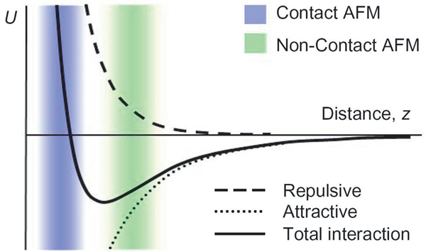 Figure 1. Interatomic force vs. distance
Because of the attractive force between the probe tip and the surface atoms, the cantilever vibration at its resonant frequency near the sample surface experiences a shift from its intrinsic spring constant (k0). This is called the effective spring constant (keff), and the following equation holds:
keff = k0 - F’ (1)
When the attractive force is applied, keff becomes smaller than k0 since the force gradient F' (=∂F/∂z) is positive. Accordingly, the stronger the interaction between the surface and the tip (in other words, the closer the tip is brought to the surface), the smaller the effective spring constant becomes. This alternating current method (AC detection) makes more sensitive responses to the force gradient as opposed to the force itself. Thus, it is also applied in such techniques as Magnetic Force Microscopy (MFM) and Dynamic Force Microscopy (DFM).
A bimorph is used to mechanically vibrate the cantilever. When the bimorph's drive frequency nears the cantilever's natural intrinsic vibration frequency (f0), resonance will take place, and the vibration that is transferred to the cantilever becomes very large. This intrinsic frequency can be detected by measuring and recording the amplitude of the cantilever vibration while scanning the drive frequency of the voltage applied to the bimorph. Figure 2 displays the relationship between the cantilever's amplitude and the vibration frequency. From this output, we can determine the cantilever's frequency.
A stiff cantilever used in True Non-Contact™ mode on the Park AFM typically has a relatively high resonant frequency, between 100 kHz and 400 kHz, with a vibration amplitude of a few nanometers. The AFM system detects changes in the resonant frequency or vibration amplitude as the tip comes near the sample surface. The sensitivity of this detection scheme provides sub-angstrom vertical resolution in the image, as with contact AFM.

Figure 2. Resonant frequency of a cantilever
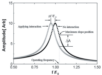
Figure 3. Resonant frequency shift
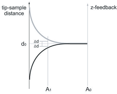
Figure 4. Resonant frequency shift
On the other hand, the spring constant affects the resonant frequency (f0) of the cantilever, and the relation between the spring constant (k0) and the resonant frequency (f0) in free space is shown as in Equation (2).
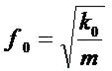 (2)
(2)
As in Equation (1), since keff becomes smaller than k0 due to the attractive force, feff too becomes smaller than f0 as shown in Figure 3. If you vibrate the cantilever at the frequency f1 (a little larger than f0) where a steep slope is observed in the graph representing free space frequency vs. amplitude, the amplitude change (ΔA) at f0 becomes very large even with a small change of intrinsic frequency caused by atomic attractions. Therefore, the amplitude change measured in f1 reflects the distance change (Δd) between the probe tip and the surface atoms.
If the change in the effective resonance frequency, feff, resulting from the interaction between the surface atoms and the probe, or the change in amplitude (ΔA) at a given frequency (f1) can be measured, the Non-Contact mode feedback loop will then compensate for the distance change between the tip and the sample surface as shown in Figure 4. By maintaining a constant amplitude (A0) and distance (d0), Non-Contact mode can measure the topography of the sample surface by using the feedback mechanism to control the Z-scanner movement following the measurement of the force gradient represented in Equation (1).

Figure 5. True Non-Contact AFM image taken with an XE-100 of 50 nm wide, 100 nm deep trenches shown in 1:1 aspect ratio 3D rendering (1 μm scan size). True Non-Contact mode from the Park AFM with high Z-servo performance can accurately trace the steep walls of the trenches.