


Basic Topographic Imaging
Park AFM's Scan System
The Park AFM's scan system is a core feature that gives acompetitive edge to Park AFM over other AFMs/SPMs. Park Systems' innovative scanner design separates the Z-scanner from the XY-scanner, enabling exceptional Z-servo performance and scan accuracy unmatched by other AFMs/SPMs. The Z-scanner, being separate from the XY-scanner, is designed to have a higher resonant frequency than conventional piezoelectric tube scanners. For this reason, a stacked piezoelectric actuator is used for the Z-scanner, and it has a very fast response speed, at least 10 kHz, with a high push-pull force when appropriately pre-loaded. Since the Z-servo response of the Park AFM's scan system is very accurate, this enables scan rates in Contact AFM & DFM that are more than 10 times faster than what is possible with a conventional tube type scanner. This increases the speed of measurements and protects the tip, resulting in the ability to acquire clear images for an extended period of time.
Contact AFM
In Contact mode of the Park AFM, also known as repulsive mode, an AFM tip makes soft "physical contact" with a sample. The tip is attached to the end of a cantilever with a low spring constant, lower than the effective spring constant holding the atoms of the sample together. As the scanner gently traces the sample under the tip, the contact force causes the cantilever to bend to accommodate changes in topography. To examine this scenario in more detail, refer to the van der Waals curve in Figure 1.
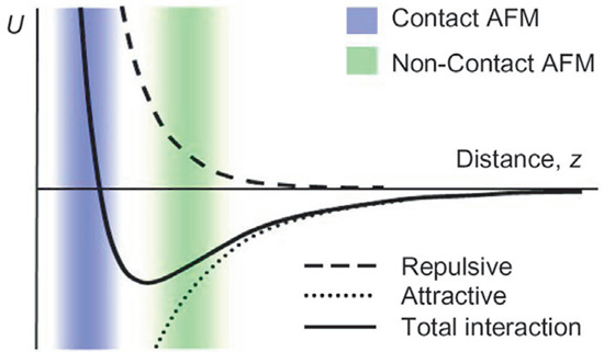
Figure 1. Inter-atomic Force vs. distance.
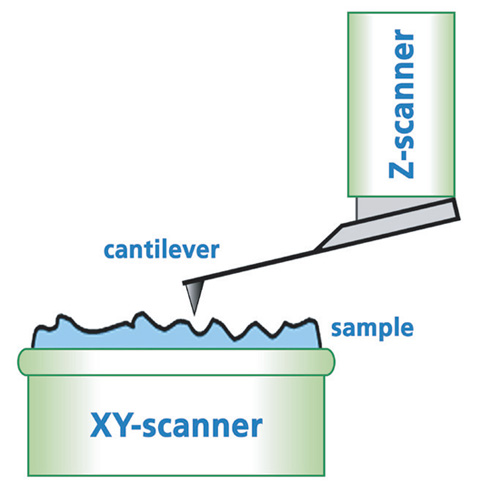
Figure 2. Park AFM scan system.
At the right side of the curve the atoms are separated by a large distance. As the atoms are gradually brought together, they first weakly attract each other. This attraction increases until the atoms are so close together that their electron clouds begin to repel each other electrostatically. This electrostatic repulsion progressively weakens the attractive force as the inter-atomic separation continues to decrease. The force goes to zero when the distance between the atoms reaches a couple of angstroms, about the length of a chemical bond. When the total van der Waals force becomes positive (repulsive), the atoms are in contact.
The slope of the van der Waals curve is very steep in the repulsive or contact region. As a result, the repulsive van der Waals force balances almost any force that attempts to push the atoms closer together. In AFM this means that when the cantilever pushes the tip against the sample, the cantilever bends rather than forcing the tip atoms closer to the sample atoms. Even if you design a very stiff cantilever to exert large forces on the sample, the inter-atomic separation between the tip and sample atoms is unlikely to decrease much. Instead, the sample surface is likely to deform (as in Nanolithography). In addition to the repulsive van der Waals force described above, two other forces are generally present during Contact mode operation of the Park AFM: a capillary force exerted by the thin water layer often present in an ambient environment as well asthe force exerted by the cantilever itself. The capillary force arises when water wicks its way around the tip, applying a strong attractive force (about 10-8 N) that holds the tip in contact with the surface. The magnitude of the capillary force depends upon the tip-to-sample separation. The force exerted by the cantilever is like the force of a compressed spring. The magnitude and sign (repulsive or attractive) of the cantilever force depends upon the deflection of the cantilever and upon its spring constant. (See Contact mode F-d Spectroscopy for more detail.)
As long as the tip is in contact with the sample, the capillary force should be constant because the distance between the tip and the sample is virtually incompressible. It is also assumed that the water layer is reasonably homogeneous. The variable force in contact mode of Park AFM is the force exerted by the cantilever. The total force that the tip exerts on the sample is the sum of the capillary force and the force by the cantilever and must be balanced by the repulsive van der Waals force for Contact mode. The magnitude of the total force exerted on the sample varies from 10-8 N (with the cantilever pulling away from the sample almost as hard as the water is pulling the tip down—see F-d Spectroscopy), to the more typical operating range of 10-7 to 10-6 N. The Park AFM is able to detect even the slightest amount of a cantilever's deflection as it moves across a sample surface. Therefore, when the cantilever scans a convex area (凸)of a sample, it will deflect upward and when it scans a concave area (凹), it will deflect downward. This probe deflection will be used as a feedback loop input that is sent to an actuator (Z-piezo). In order to produce an image of the surface topography, the Z-piezo will maintain the same cantilever deflection by keeping a constant distance between the probe and the sample.
The Park AFM detects the position of the cantilever with optical techniques. In the scheme, shown in Figure 2, a laser beam bounces off the back of the cantilever onto a position-sensitive photo detector (PSPD). As the cantilever bends, the position of the laser beam on the detector shifts. The PSPD itself can measure displacements of light as small as 10Å. The ratio of the path length between the cantilever and the detector to the length of the cantilever itself produces a mechanical amplification. As a result, the system can detect sub-angstrom vertical movement of the cantilever tip.
Other methods of detecting cantilever deflection rely on optical interference, or even a scanning tunneling microscope tip to read the cantilever deflection. One particularly elegant technique is to fabricate the cantilever from a piezoresistive material, creating a so-called self-actuating cantilever, so that its deflection can be detected electrically. In piezoresistive materials, strain from mechanical deformation causes a change in the material's resistivity. For piezoresistive detection, a laser beam and a PSPD are not necessary.
Once cantilever deflection is detected in Contact mode with Park AFM, the topographic data is generatedby operating in one of two modes— constant-force or constant-height. In constant-force mode, the deflection of the cantilever can be used as input to a feedback circuit that moves the scanner up and down in Z, responding to the topography by keeping the cantilever deflection constant. In this case, the image is generated from the scanner's motion. With the cantilever deflection held constant, the total force applied to the sample is constant. In constant-force mode, the speed of scanning is limited by the response time of the overall feedback circuit, but the total force exerted on the sample by the tip is well controlled. Constant-force mode is the default Contact mode in Park AFM and is preferred for most applications.
Constant-height mode is often used for taking atomic-scale images of atomically flat surfaces. Here, the Z-servo is turned off and a sample is scanned without Z-feedback. Instead, the cantilever deflection error signal is directly used to generate the topographic data set because the height of the scanner is fixed as it scans. The cantilever deflections and thus variations in applied force are small. Constant-height mode is essential for recording real-time images of changing surfaces where high scan speed is required.
Dynamic Force Microscopy (DFM)
Dynamic Force Microscopy (DFM) is very similar to True Non-Contact™ mode inPark AFM in many ways such as the applied force and the measurement principle. DFM is a hybrid of the two most fundamental measurement methods, represented by contact mode and True Non-Contact™ mode. In DFM with Park AFM, the cantilever vibrates in free space in the vicinity of the resonant frequency like in Non-Contact mode while also getting very close to the sample surface, tapping it repeatedly. The tip contacts the sample surface as in Contact mode.
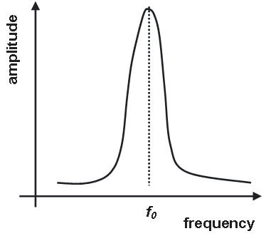
Figure 3. Resonant frequency of a cantilever
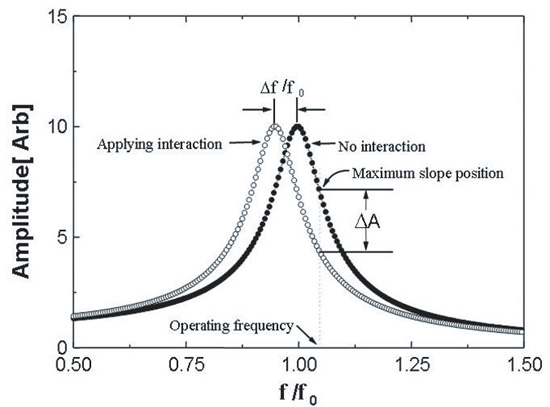
Figure 4. Resonant frequency shift as the tip approaches sample surface
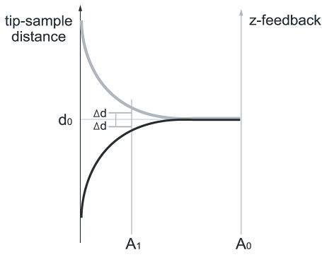
Figure 5. TIp-sample distance vs. amplitude change as the tip approaches sample surface
If the vibration amplitude of the cantilever used in DFM is measured while changing the frequency, as shown in Figure 3, a special frequency appears where the amplitude resonates and amplifies greatly. This is called the intrinsic frequency (f0). DFM with Park AFM uses the Non-Contact mode feedback circuit to keep the vibrating frequency (f1) a little bit lower than the resonant frequency while oscillating in free space. Note that non-contact AFM uses the vibrating frequency higher than the resonant frequency. As the tip is lowered, the real spring constant reduces due to the attractive van der Waals force which becomes larger as the tip comes closer to the sample surface, as shown in Figure 4. Therefore the resonant frequency changes to effective frequency (feff) in the Non-Contact region and the amplitude at the frequency f1 increases by ΔA. Since the amplitude increases by ΔA, the Non-Contact mode feedback circuit decreases the distance between the tip and the sample surface by Δd, indicated in the graph of vibration amplitude vs. tip-sample distance and Z-feedback as shown in Figure 5. Therefore the vibrating cantilever, which is oscillating above the sample, approaches the sample almost in contact or in collision with the surface. This method, keeping intermittent contact between the sample surface and the vibrating cantilever is called Dynamic Force Microscopy (DFM).
Similar to the initial approach of making contact with the sample while scanning, larger amplitude reduces the distance between the tip and sample and smaller amplitude increases the distance depending on the surface's roughness to its topology. DFM with Park AFM has an advantage over Contact mode in the sense that it will not damage the sample as much since there is no drag, frictional, or lateral force acting on the sample. However, its contact force will inevitably damage the tip and degrade a sample surface (see "True Non-Contact™ mode vs. Tapping Imaging"). The resolution of DFM, however, is not as high as that of True Non-Contact™ mode with Park AFM, since the very sharp end of a tip is extremely fragile and becomes more blunt each time it makes violent contact with the sample.
It must be noted that the tip-sample impact force in tapping imaging is so great that it is destructive. Tapping imaging may eliminate the lateral frictional force, but the tip-sample impact force is greater than in typical Contact mode AFM. This force results in significant tip wear, which is bound to limit spatial resolution and, even worse, the sample can be irreparably damaged. This is even more so a problem in the case of imaging soft materials (see "True Non-Contact AFM for biological samples").